OVERVIEW
The Vortex Flow Meter works by placing a bluff body in the flow path, which creates vortices downstream. The frequency of these vortices is proportional to the flow velocity, allowing precise measurement of flow rate. It is suitable for liquids, gases, and steam in industrial processes, offering robust performance even in high-temperature and high-pressure environments. These meters are commonly used in chemical, water treatment, HVAC, and energy sectors for process control and monitoring.
Working Principle
The Vortex Flow Meter operates on the vortex shedding principle. When air flows past a bluff body inside the meter, vortices are generated alternately on both sides. The frequency of these vortices is directly proportional to the air velocity. Sensors detect this frequency and convert it into an electrical signal to calculate the air flow rate accurately.
MAIN PARAMETERS
| Flow Range |
Depends on model (typically 0.1–50 m/s) |
| Pipe Size |
DN15 – DN300 (or as per model) |
| Medium |
Liquids, gases, or steam |
| Accuracy |
±0.5% – ±1.0% of reading |
| Operating Temperature |
-40°C to 400°C (depending on model) |
| Operating Pressure |
Up to 40 bar (depending on model) |
| Output Signal |
4–20 mA, Pulse, or Frequency output |
| Connection Type |
Flanged or Threaded |
| Material |
Stainless steel, Carbon steel, or Alloy steel |
| Power Supply |
24V DC / 110–220V AC (depending on model) |
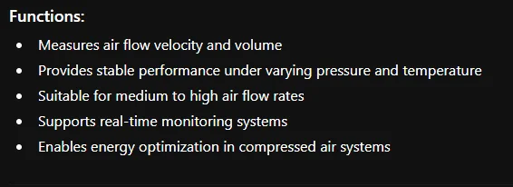
Functions